Note: This document is not yet complete. It may contain inaccuracies.
The output relays on the HIO16 all have a single normally open contact. Connection is via the quick connect tabs on top of the relays.
Because of the possibly high voltages and currents involved, you must observe certain precautions:
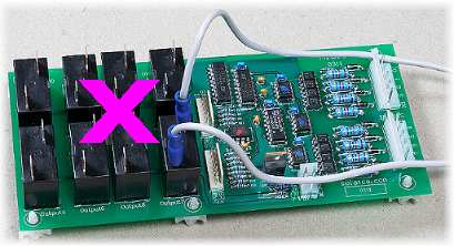
The above photo shows how not to wire an output relay. The problems here are:
a) The relay current is flowing through what amounts to a large loop or coil with the board's logic circuitry right in the middle. This maximises the chances of any magnetic fields generated in the wires inducing currents into the board and upsetting the circuitry on the board. Such magnetic fields are generated by the current flowing through the wires.
b) The wires pass low down and close to the board. This maximises the chances of electric fields generated in the wires from radiating into the circuitry on the board and causing problems. Such electric fields are caused by sudden voltage changes in the wires when the relays switch (especially switching off). The voltages induced when switching off a motor can amount to brief "spikes" of thousands of volts with very rapid rise and fall times.
c) The close proximity of the wires to the board also potentially compromise the safety rating of the setup. If they actually touch the components it means you only have the single layer of wire insulation between the high voltage on the relay contacts and the "safe" ELV side.
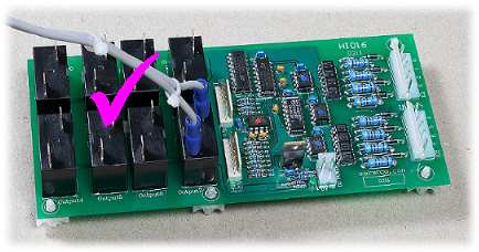
The above picture shows a better way of doing it. Here the wires from the relay are routed up and away from the board, and the have been tied together to prevent a loop of wire from being formed. In a real situation it would also usually be necessary to physically restrain the wires so they cannot accidentally move and touch the board.