CC18: Bidirectional points used as outputs
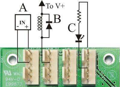
The picture above illustrates the bidirectional I/O points connected to some typical output loads. When an output is ON it connects the I/O pin to 0V via a Darlington transistor.
Each of the fours connectors is wired to 4 bidirectional I/O pins. Each connector also has a "convenience" pin connected to power supply positive. The output load should always be connected between the output pin and power supply positive. Use the Supply+ convenience pin in preference to wiring directly to the power supply +.
CAUTION: Take care never to short an output pin to the positive common pin. If the output is on at the time you will blow up the output chip instantly!
The loads illustrated are:
A: The input pins of a solid state relay. Note the polarity!
B: A relay coil. Notice we have included a catch diode across the coil. While there are diodes on the board we strongly recommend a diode across the coil, as close as possible to the coil, to minimize problems with switching noise. A suitable diode is a 1N4001 or similar 1A/50V rectifier diode.
C: An LED, with a series current limiting resistor. Resistance calculators
You will (of course!) have noticed that for A and C we returned the loads to V+ by way of the convenience outlet pins on the boards, whereas for B we have shown the connection to be to V+ elsewhere (presumable directly to the power supply). There are two reasons for this:
- In general, you can do whatever is most convenient.
- Notwithstanding 1 above, there is some advantage in returning higher current loads directly to the power supply, especially inductive loads like relay coils and solenoids. By not having the supply currents of these loads flow through the controller there is less chance of the noise "spikes" they generate interfering with the controller.
The (digital) outputs are implemented using the ULN2803A, a chip that contains Darlington transistors. The outputs consist of transistor switches between the output pin and 0V. When the output transistor is off, a multimeter set to DC volts connected between the output and 0V will measure a voltage slightly less than the positive supply voltage.
Take care never to short the output pin to the positive supply voltage. If the output turns on the output chip will be instantly destroyed. This includes never doing it with a multimeter set on a current range.
There are catch diodes built into the chip. This means the board will not be damaged if you are driving relay coils, solenoid valves or other inductive loads (within the ratings of the output). We nevertheless recommend external catch diodes connected directly to the relay coil as close as possible to the relay, in order to reduce adverse effects of switching noise. The onboard diodes also mean that the load must not be connected to a supply voltage greater than the board's positive supply voltage.
Maximum allowable output current
The maximum allowable output current is 400mA steady state, with brief (100mS) peaks of 500mA allowed. There is also a limit to how much total current one ULN2803A chip can handle. This relates to the internal heating of the chip.
Let's look at 2 extreme cases:
- All 8 outputs on one chip conducting the same current
- The allowable current concentrated in a few outputs.
Equal currents
The following table lists allowable current versus ambient temperature, when all 8 outputs are conducting the same current at once:
| Temperature | Allowable current per output |
|---|---|
| 25°C | 180mA |
| 40°C | 160mA |
| 50°C | 145mA |
| 60°C | 130mA |
| 70°C | 115mA |
Concentrated currents
The following table shows the maximum allowable currents, when concentrated in a few outputs, versus temperature
| Temp | 1st O/P | 2nd O/P | 3rd O/P | 4th O/P |
|---|---|---|---|---|
| 25°C | 400mA | 400mA | 300mA | 0 |
| 40°C | 400mA | 400mA | 150mA | 0 |
| 50°C | 400mA | 400mA | 0 | 0 |
| 60°C | 400mA | 325mA | 0 | 0 |
| 70°C | 400mA | 220mA | 0 | 0 |
Naturally there are many other possible combinations, but the above should serve as a guide.
The above figures are intended as a guide only. In any event, the absolute maximum operating temperature for the ULN2803A chip is 70°C.
If you feel like doing the actual sums, here's the procedure.
- For each output, calculate its output voltage drop from the formula
V(out) = 0.92 + 1.85 * I(out) [ I(out) in Amperes ] - For each output calculate the dissipation in watts from the formula
P=V(out) * I(out) - Add up all the dissipation figures to give P(tot) in watts
- Calculate the maximum allowable ambient temperature from the formula
Ta(max) = 125 - P(tot) * 55 - If you get an answer over 70°C then use 70°C
This calculation aims at a maximum internal (junction) temperature of 125°C, which is the maximum rating of the chip. There are 2 things to keep in mind with this:
- A semiconductor will not suddenly die if you exceed the temperature rating by a modest amount
- As a rule of thumb, every 10°C reduction in temperature doubles the life-time (halves the failure rate).
Hence, an occasional excursion to, or even above, the rated temperature isn't the end of the world. However, for long life the cooler the better.
Note: This discussion pertains to the maximum operating temperature for the ULN2803A output chip only. See CC18 Operating temperature ratings for a further discussion.
How to blow up the outputs
Here are some of the ways you can blow up the outputs:
- Connecting the output pin directly to the positive supply voltage (or to any other voltage source capably of delivering more than the output current rating)
- Connecting the output pin to any negative voltage
- Connecting the output pin to any voltage greater than the positive supply.
- Switching a load that has a large amount of capacitance, i.e. draws large surge current. This could be the case if you tried using an output to activate some other piece of equipment by switching its DC power on and off.
- Using an AC solenoid or relay coil in place of a DC coil. An AC coil will typically draw 10 to 15 times its rated current if accidentally used in a DC circuit.