SPLat Logo

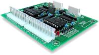
XBIO16 16 point expansion board

NOTICE: Our web site is being updated, but is currently experiencing extreme slowness due to host issues. Please contact us directly.
NOTICE: SPLat Controls has moved. We are now at 1/85 Brunel Rd, Seaford, 3198. map
SPLat will be shut down for the Christmas Holiday season from Friday 20 December 2024 through Tuesday 7 January 2025. We will check emails periodically and will continue to process orders but at a slower pace. Santa hat

The XBIO16 adds 16 digital I/O points to your SPLat controller. It is easy to use, appearing simply as another 16 inputs and 16 outputs. You can use each point as one or the other. No explicit initialization is required.

As outputs the XBIO bidirectional I/O points use a solid state Darlington switches between the pin and ground (0V). The load (say a solenoid coil) has to be connected between the output pin and the positive supply voltage. The maximum allowable output current is up to 400mA steady state, 500mA peak. There are onboard catch diodes, so it is safe driving inductive, non-motor loads up to the rated current. For motors the locked rotor current must be within the output rating. See the documentation for more detail, including allowable output currents when multiple outputs are on at once.

As inputs the XBIO bidirectional I/O points provide industry standard NPN compatibility. Tying the input pin to ground (0V) registers as an On (True/logic 1) state. Leaving it open circuit or driving it to the positive supply voltage registers as an Off (False/logic 0). See the documentation for more detail.

Technical documentation SPice/Xwire peripheral board overview page Compare with other I/O expansion boards
The "up to" figure is just that: A maximum rating, beyond which the board may be damaged.

Some of our competitors leave it at that. They pick the absolute maximum rating out of the data sheet for the component they are using, and quote that as what you can do with their product, with no additional qualifications.

We try to be better than that. Sure, we quote an "up to" headline figure, though even that is carefully tempered by consideration of the overall design of the board, and how you are likely to use it. But then we go the next step and give you some information on how far you can push the board without compromising long term reliability. That extra information is in the board's technical data.

If this leaves any unanswered question about using our boards in your product, feel free to ask us via our contacts page. Our support comes from the actual engineers who designed the product, not via a forum.

XBIO16

Cable, connectors and standoffs included but not shown

XBIO16DK
Developers kit, contains the expansion board with 16BIO, 600mm shielded cable, matching connectors and mounting standoffs.
  • 1 - 4AUD89exGSTUSD≈68
  • 5 - 9AUD87exGSTUSD≈67
  • 10 - 24AUD86exGSTUSD≈65

Shipping weight:
190g / 6.7oz

missing image
ULNX6
Pack of 6 spare ULN2803A output chips
  • 1 - 4AUD22exGSTUSD≈17
  • 5 - 9AUD21exGSTUSD≈16
  • 10 - 24AUD20exGSTUSD≈16

Shipping weight:
25g / 0.9oz