DA8 I/O Map
Here is the I/O map in SPLat equate format for the DA8
There's some really good technical information about using digital pins as outputs.
;-- digital inputs --
iIn0              iEQU  0
iIn1              iEQU  1
iIn2              iEQU  2
iIn3              iEQU  3
iDipSw0           iEQU  4
iDipSw1           iEQU  5
iDipSw2           iEQU  6
iDipSw3           iEQU  7

;-- digital outputs --
oOut0             oEQU  0
oOut1             oEQU  1
oOut2             oEQU  2
oOut3             oEQU  3
oLedOn            oEQU  4
oLedGreen         oEQU  5

;-- analogue inputs --
aiIn0             EQU   0
aiIn1             EQU   1
aiIn2             EQU   2
aiIn3             EQU   3
aiIn4             EQU   4
aiIn5             EQU   5
aiIn6             EQU   6
aiIn7             EQU   7

;-- analogue outputs --
aoOut0            EQU   0
aoOut1            EQU   1
aoDout0           EQU   2           ; Dout 0 as an analogue output
aoDout1           EQU   3           ; Dout 1 as an analogue output
aoDout2           EQU   4           ; Dout 2 as an analogue output
aoDout3           EQU   5           ; Dout 3 as an analogue output
; NOTE that aoDout0-aoDout3 are not mapped to the default Xwire SEXi app (unless the DA8 is running version 5.0 or 5.1 of the firmware)

;-- serial --
COMTTL            EQU   251
COM485            EQU   252
COMUSB            EQU   253
The 4 digital I/O terminals are all active low, inactive o/c (open circuit). You do not need to specifically configure them as inputs or outputs, they are simply always inputs and always outputs. Be aware that to use a pin as an input, be sure not to use an output instruction to turn it on, otherwise it will switch low and can't be used as an input.
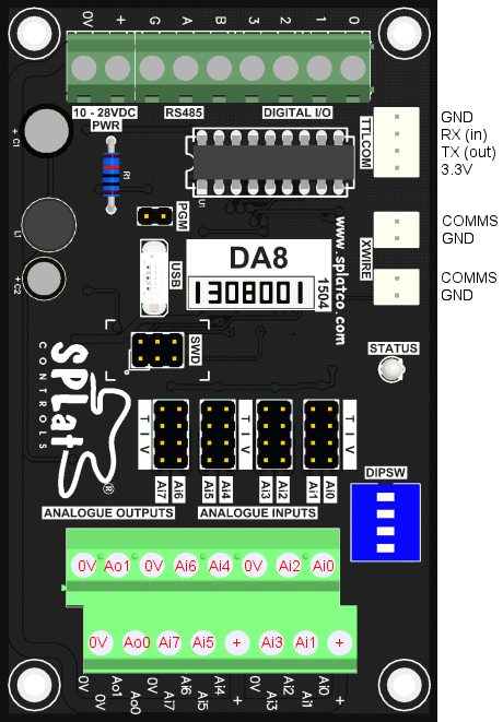
This picture shows the pin functions for the TTL Serial connector and Xwire connector (both Xwire connectors are identical). It also clarifies confusion ove analogue input and output functions.
As a side note, separation of the LED into on/off and green/red pins allows for some cute effects. For example:
   On    oLedOn
   Blink oLedGreen
These two instruction will cause the LED to automatically start blinking between red & green.